


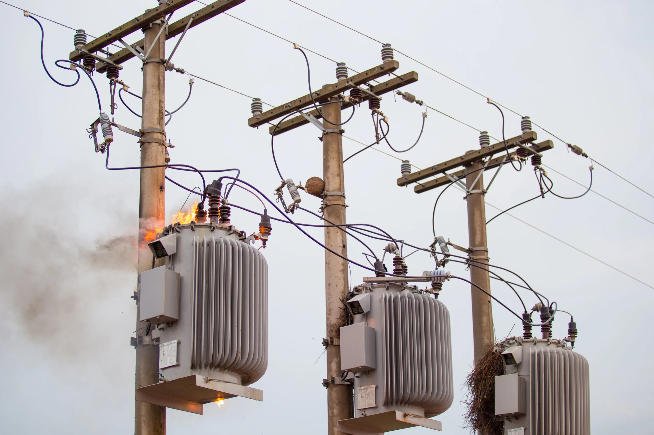
Overhead distribution transformers are among the most reliable assets in the power grid, yet when they do fail, the consequences can be severe. Though inherent failure rates for transformers may be as low as 0.0041 failures per year, the bulk of feeder outages (≈75%) stem from external causes, whereas component failures, while less frequent, tend to be far more catastrophic.
In this post, we’ll explore the major failure modes for overhead transformers, present prevention strategies, and review the diagnostic tooling and lineman protocol required if you want to learn more about Divergent Alliance and how we support electrical utility companies across the U.S.
Strategic Imperative: Risk, Reliability & ROI
Reliability Metrics and the High Cost of Catastrophe
The typical lifespan of a transformer is around 20 years, but it could be more or less depending on conditions, giving utilities confidence in long‑term reliability. But that reliability must be framed against the operational risk environment. External factors (storm damage, wildlife, and conductor contact) account for about 75% of sustained outages; component failures—though only ~15%—carry very high consequences.
For example, bushing failures contribute to up to 20% of major transformer failures worldwide, with nearly half resulting in an explosion or fire. The high cost of a single event justifies proactive condition monitoring and targeted maintenance. Hence, the shift from calendar‑based maintenance to a Condition‑Based Monitoring (CBM) model allows utilities to intervene precisely when needed rather than following fixed schedules.
The Evolution to CBM
Traditional time‑based maintenance is inherently inefficient because it fails to detect faults that develop between intervals. Predictive maintenance, by contrast, focuses on real‑time condition data—Dissolved Gas Analysis (DGA), Turns Ratio (TTR) tests, and infrared thermography—all carried out by linemen on‑site using certified equipment. The adage “Garbage In, Garbage Out” applies: the success of CBM depends on accurate data acquired in the field.
For example, portable TTR testers must meet ANSI/IEEE C57.12.90, and IR cameras should have minimum resolutions and accuracy thresholds (<2 % error) for meaningful hotspot detection.
Putting this strategy in action often yields payback within 18‑36 months and extends Mean Time Between Failures (MTBF).
Common Overhead Transformer Failure Causes
Transformers seldom fail for a single reason. More often, they degrade under combined electrical, thermal, mechanical, or environmental stress until a triggering event causes failure.
Electrical Failure Modes: Dielectric Breakdown & Surge Management
- The most common electrical failures begin with insulation damage: turn‑to‑turn breakdown, flashovers, or internal arcing.
- Transient overvoltage, lightning strikes, or switching surges accelerate insulation degradation. Partial Discharge (PD) is an insidious form of failure where localized discharges degrade insulation over time.
- Power cables, bushings, and surge arrestors must be inspected regularly. If a fault current occurs, mechanical stress on windings can deform them and reduce longevity.
Thermal Failure Modes: Insulation Aging & Hot Spot Dynamics
- Overloading, high ambient temperature, and inadequate cooling all accelerate aging of cellulose insulation; for each 10 °C rise above rated temperature, insulation life may halve.
- Internal hotspots often stem from non‑linear loads (VFDs), blocked radiator banks, or broken cooling fans. Thermographic scans are critical to find abnormal cooling patterns.
- Importantly, thermal degradation weakens the insulation system, making even normal electrical stresses more likely to cause catastrophic failure.
Mechanical & Environmental Stressors
- Mechanical stress arises from winding deformation, vibration, loose clamping, and transport damage. These stresses may manifest long before failure.
- Environmental threats: moisture ingress, humidity, airborne dust, and corrosive gases—all reduce dielectric performance and accelerate aging. Moisture in particular impairs insulation and can cause flashover.
- Bushings: A critical high‑risk component. Bushing failures account for ~20% of major transformer breakdowns—and nearly half lead to catastrophic outcomes. PD, moisture ingress, and aging all contribute.
Predictive & Diagnostic Strategies: Tools for Intervention
Dissolved Gas Analysis (DGA)
DGA identifies gases dissolved in the transformer oil—each gas type correlates to a specific fault (e.g., acetylene for arcing, hydrogen for PD). Sampling must be precise: clean port, flush oil, evacuated container. Poor sample quality compromises the analysis entirely.
Recent ML techniques applied to DGA data have shown near‑100 % accuracy—but only when sample procedures are rigorously executed.
Thermal Monitoring & Hotspot Detection
Infrared thermography captures surface thermal signatures. Abnormal patterns—such as cold radiator banks next to hot ones—indicate internal flow or heat dissipation problems. But remember, IR only reveals surface anomalies, not internal hotspots.
Electrical Integrity Testing (Offline Field Checks)
- Turns Ratio Testing (TTR): Verifies HV/LV winding ratio and detects shorted turns. Must comply with ANSI/IEEE C57.12.90.
- Insulation Resistance (Megger) Testing: Measures insulation system health (phase‑to‑phase, phase‑to‑ground). Typical output: 5 kV or 10 kV.
Equipment Requirements
| Category | Required Equipment | Key Measurement | Standard | Lineman Requirement |
| DGA | Sampling Syringes & Kits | H₂, C₂H₂ concentrations | Lab Analysis | Clean, air‑free sampling method |
| Electrical Integrity | Portable TTR Tester | Turns ratio, polarity, shorted turns | ANSI/IEEE C57.12.90 | Battery‑powered, fast testing |
| Insulation Health | Megger (Insulation Tester) | Dielectric resistance | — | ≥ 5kV/10kV output |
| Thermal | IR Thermal Camera | Surface temperature anomalies | 320×240 res, <2% accuracy | Safe distance scanning |
Linemen Field Procedures, Safety & Equipment Mandates
Core Safety Protocols: PPE & Grounding
Linemen must wear insulating gloves, dielectric boots, arc‑rated clothing, and use fall‑arrest systems when working overhead. OSHA Minimum Approach Distance (MAD) rules (29 CFR 1926.1408) must always be followed.
Protective grounding is mandatory: Equipotential Zone (EPZ) grounding is now preferred over bracket grounding because it minimizes potential differences across the work area. High‑quality grounding sets are essential.
Routine Inspection Protocols
Daily visual checks:
- Inspect the tank for leaks, gaskets, and corrosion
- Check bushings for cracks, contamination
- Verify cooling ducts are clear
Connections: check torque, temperature, surge arrestor condition
Procedural sampling: perform oil sample via clean port, flush, draw into evacuated syringe
Specialized Tooling for Field Crews
Tools must be insulated, rugged, and rated for high-voltage environments:
- Insulated hand tools (torque wrenches, pliers)
- Hot‑line tools (telescopic sticks, shotgun sticks)
- Rigging gear (lid lifters, hoists)
Preventing Catastrophic Failure: The Case for Proactive Transformer Maintenance
Failures in overhead transformers may be low‑frequency, but their impact is disproportionately high. A modern maintenance paradigm places condition‑based monitoring, targeted diagnostics, and high‑quality tooling at the center. By combining effective diagnostic protocols, rigorous field procedures, and certified equipment, utilities can dramatically reduce failure risk, improve safety, and lower the total cost of ownership.
For linemen and field crews, the stakes are clear: your tools and procedures are your first line of defense. With the right investment in quality diagnostic equipment and safety‑certified tooling, catastrophic failure becomes preventable, not just predictable. Contact Divergent Alliance today to talk about tooling and how we can support you and your crew!
FAQs
What are the most common failures in overhead transformers?
Overhead transformer failures typically fall into electrical, thermal, mechanical, or environmental categories—turn‑to‑turn insulation breakdown, bushing failure, overheating, vibration, moisture ingress, and surge damage are all frequent culprits.
How often should overhead transformer bushings be replaced?
Bushing replacement does not follow a fixed calendar interval. Instead, condition‑based monitoring should drive replacement: look for rapid changes in capacitance or dissipation factor, PD activity, or visible cracking. Because nearly half of bushing failures result in catastrophic damage, relying solely on scheduled replacement is no longer the best practice.
Can thermal imaging replace oil testing (DGA)?
No. Thermal imaging is a valuable non‑destructive tool for detecting surface hotspots or blocked cooling, but it cannot detect internal insulation degradation or gas generation in the oil. DGA remains the gold standard for internal fault detection.
What is an acceptable load rating for an overhead transformer to avoid thermal failure?
Load ratings depend on insulation class, ambient conditions, and cooling system design. Generally, operating continuously above rated capacity or under high harmonic distortion (e.g., from VFDs) increases risk. Utilities should consult IEEE C57.110 guidelines for derating in harmonic environments.
What tools are essential for a lineman working on overhead transformer maintenance?
Key tools include TTR testers (ANSI/IEEE C57.12.90 compliant), insulated hand tools, EPZ grounding sets, IR cameras (320×240 res, <2 % accuracy), hot sticks, and insulated torque tools. Without proper tooling, condition monitoring and safe field work suffer.